

 Türkçe
 Русский
 Español
 العربية
Hydraulic Cylinder Sizing: How to Select Bore, Rod and Stroke
To size a hydraulic cylinder, work out the force the load needs and add a safety margin, divide it by the working pressure to get the piston area and bore, check the rod against buckling for the stroke and mounting, and finally set the pump flow for the speed you need with Q = A × v.
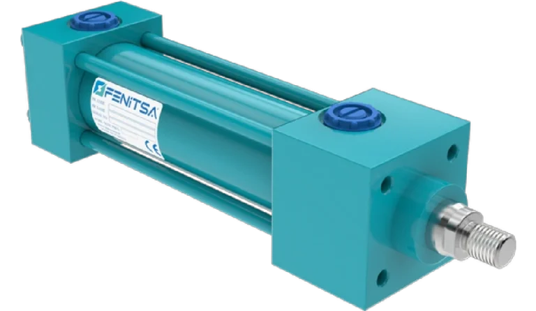
This guide walks through the hydraulic cylinder calculations for each step, with tables and a worked example; the hydraulic cylinder force calculator does the arithmetic for any bore and pressure. Values for Fenitsa hydraulic cylinders come from our FDH catalogue: Ø40–Ø200 mm bores, 160 bar and strokes up to 5,000 mm.
Step 1: Required Force and Safety Factor
Start with the force at the worst point of the stroke. For a vertical lift it is the weight, F = m × g; for a sliding load, F = μ × m × g; on an incline, F = m × g × (sin α + μ × cos α). Add the force to accelerate the load (F = m × a) and any process forces.
Through a lever, the rod force is the load force times the lever-arm ratio, divided by the sine of the angle between cylinder and lever; check both ends of the stroke.
Then add a margin — typically a factor of 1.2–1.5, towards the upper end for shock, uncertain friction or long hose runs — and divide by the mechanical efficiency explained below.
Fload = m × gFdesign = Fload × S / ηStep 2: Working Pressure
The working pressure is the pressure at the cylinder port while the load moves: the relief valve setting minus the losses in valves, hoses and fittings. Size on that figure, not on the pump’s maximum.
A higher pressure gives a smaller bore, less oil and a lighter cylinder; a lower pressure gives gentler control and longer seal life. Fenitsa FDH cylinders are rated for 160 bar (2,321 psi) and tested at 240 bar, with a 250 bar (3,626 psi) option when space is tight.
Step 3: Bore from Force
Bores in mm, rounded up to FDH standard sizes.
A = F / pD = √(4 × F / (π × p))With the force in newtons and the pressure in N/mm² (1 bar = 0.1 N/mm²), the piston area is A = F / p and the bore D = √(4A / π). Round up to the next standard bore — never down — and recalculate the real force.
| Design force | Required at 160 bar | Standard bore | Force at 160 bar | Required at 250 bar | Standard bore | Force at 250 bar |
|---|---|---|---|---|---|---|
| 5 t (49.0 kN) | Ø62.5 | Ø63 | 5.1 t | Ø50.0 | Ø50 | 5.0 t |
| 10 t (98.1 kN) | Ø88.3 | Ø100 | 12.8 t | Ø70.7 | Ø80 | 12.8 t |
| 20 t (196.1 kN) | Ø124.9 | Ø125 | 20.0 t | Ø99.9 | Ø100 | 20.0 t |
| 30 t (294.2 kN) | Ø153.0 | Ø160 | 32.8 t | Ø122.4 | Ø125 | 31.3 t |
| 50 t (490.3 kN) | Ø197.5 | Ø200 | 51.3 t | Ø158.0 | Ø160 | 51.3 t |
| 100 t (980.7 kN) | Ø279.4 | Built to order | — | Ø223.5 | Built to order | — |
Forces are in metric tonnes-force (1 t = 9.81 kN). Bores above Ø200 mm are built to order. For pull force or other pressures, use the hydraulic cylinder calculator.
Step 4: Rod Diameter and Buckling
In tension the rod is rarely critical; in compression at full extension a long, slender rod behaves like a column. The stroke and the mounting — not the pressure — decide the rod size.
Fk = π² × E × I / Lk²I = π × d⁴ / 64Lk = K × LUse E = 210,000 N/mm² for steel. L is the free length at full extension — pin to pin for a cylinder pinned at both ends — and K the mounting factor below. Divide Fk by a safety factor (3.5 is common engineering practice); the result must be at least the maximum push force on the rod.
| Mounting and rod-end guidance | Euler case | K | L_k |
|---|---|---|---|
| Fixed (flange or foot), rod end free and unguided | Case 1 | 2.0 | 2.0 × L |
| Pinned at both ends: rear clevis (RSM, RHM) and rod-end clevis or spherical eye (FSM, FRM) | Case 2 | 1.0 | 1.0 × L |
| Fixed (flange or foot), rod end pinned and guided | Case 3 | 0.7 | 0.7 × L |
| Fixed, rod end fixed and rigidly guided | Case 4 | 0.5 | 0.5 × L |
Real mountings are never perfectly rigid, so many engineers use case 2 (K = 1) for pinned cylinders and take no credit for case 4; a centre trunnion (CTM) lies between cases 1 and 2.
| Rod | Used on bores | L_k 1,000 mm | L_k 2,000 mm | L_k 3,000 mm | L_k 5,000 mm |
|---|---|---|---|---|---|
| Ø25 mm | Ø40 | 11.4 | 2.8 | 1.3 | 0.5 |
| Ø28 mm | Ø40, Ø50 | 17.9 | 4.5 | 2.0 | 0.7 |
| Ø30 mm | Ø50 | 23.5 | 5.9 | 2.6 | 0.9 |
| Ø36 mm | Ø50, Ø63 | 48.8 | 12.2 | 5.4 | 2.0 |
| Ø45 mm | Ø63, Ø80 | 119.2 | 29.8 | 13.2 | 4.8 |
| Ø56 mm | Ø80, Ø100 | — | 71.5 | 31.8 | 11.4 |
| Ø70 mm | Ø100, Ø125 | — | 174.5 | 77.5 | 27.9 |
| Ø90 mm | Ø125, Ø160 | — | 476.8 | 211.9 | 76.3 |
| Ø100 mm | Ø160 | — | — | 323.0 | 116.3 |
| Ø110 mm | Ø200 | — | — | 472.9 | 170.2 |
| Ø125 mm | Ø200 | — | — | — | 283.9 |
— = not limiting: buckling allows more than the biggest bore on that rod can push at 250 bar. Euler applies to slender rods only.
Step 5: Stroke and Speed (Q = A × v)
Stroke comes from the machine geometry: the travel the load needs, plus a small margin so the piston does not act as the machine’s end stop. Fenitsa FDH standard strokes are 100, 200, 300, 400 and 500 mm, with a maximum of 5,000 mm.
Speed follows from flow. Retraction is faster than extension, and more oil leaves the cap side than the pump delivers, so size the return line for it. Keep piston speed within 0.5 m/s, the FDH rating.
Q [L/min] = A [cm²] × v [cm/s] × 0.06P [kW] = p [bar] × Q [L/min] / 600| Bore | Area (cm²) | 0.05 m/s | 0.1 m/s | 0.2 m/s | 0.5 m/s |
|---|---|---|---|---|---|
| Ø40 mm | 12.6 | 3.8 | 7.5 | 15.1 | 37.7 |
| Ø50 mm | 19.6 | 5.9 | 11.8 | 23.6 | 58.9 |
| Ø63 mm | 31.2 | 9.4 | 18.7 | 37.4 | 93.5 |
| Ø80 mm | 50.3 | 15.1 | 30.2 | 60.3 | 150.8 |
| Ø100 mm | 78.5 | 23.6 | 47.1 | 94.2 | 235.6 |
| Ø125 mm | 122.7 | 36.8 | 73.6 | 147.3 | 368.2 |
| Ø160 mm | 201.1 | 60.3 | 120.6 | 241.3 | 603.2 |
| Ø200 mm | 314.2 | 94.2 | 188.5 | 377.0 | 942.5 |
Example: a Ø100 mm cylinder extending at 0.1 m/s needs 47.1 L/min, or 12.6 kW of hydraulic power at 160 bar. The hydraulic flow rate calculator converts flow and speed for any size.
Hydraulic Cylinder Efficiency and Friction Losses
A hydraulic cylinder turns most, but not all, of its pressure into force. Seal friction typically leaves a mechanical efficiency of about 85–95 %. Losses are proportionally larger at low pressure, with tight new seals and at very low speed, where breakaway friction exceeds running friction and can cause stick-slip.
Volumetric losses in a healthy cylinder are close to zero. The bigger losses are pressure drops in valves and hoses — hence step 2 uses the pressure at the cylinder.
Factual = p × A × ηmExample: a Ø100 mm cylinder at 160 bar has a theoretical push force of 125.7 kN; at a mechanical efficiency of 0.9 it delivers about 113.1 kN.
Worked Example: Hydraulic Cylinder Calculation for a Lifting Platform
Task. A platform and its load weigh 5,000 kg and must be lifted 900 mm in 9 s. The cylinder is vertical and pinned at both ends (rear clevis and rod eye), with an extended pin-to-pin length of 2,000 mm. The power unit gives 160 bar at the cylinder. Safety factor 1.25, mechanical efficiency 0.9.
1 — Force. Load force = 5,000 × 9.81 = 49.03 kN; with the safety factor 61.29 kN; design force 61.29 / 0.9 = 68.10 kN.
2 and 3 — Pressure and bore. 160 bar = 16 N/mm², so A = 68,102 / 16 = 4,256 mm² and D = 73.6 mm. The next standard bore is Ø80 mm: 80.4 kN (8.20 t) at 160 bar.
4 — Rod. FDH rods for Ø80 mm are Ø45 and Ø56 mm; pinned at both ends, K = 1 and Lk = 2,000 mm. Ø45 mm: Fk = 104.3 kN, permissible 29.8 kN — less than the 61.3 kN factored load. Ø56 mm: Fk = 250.1 kN, permissible 71.5 kN — enough for the 61.3 kN factored load. The Ø56 mm rod is chosen.
5 — Speed and flow. v = 900 / 9 = 100 mm/s, so Q = A × v = 30.2 L/min. Lifting the load actually needs Fload / (A × η) = 108 bar, well inside 160 bar, and 108 × 30.2 / 600 = 5.4 kW of hydraulic power. Retracting with the same flow on the 25.6 cm² annulus gives 196 mm/s, within 0.5 m/s, while 59.1 L/min leaves the cap side.
Try your own numbers in the hydraulic cylinder calculator, then check the rod with the buckling table above.
- BoreØ80 mm
- RodØ56 mm
- Stroke900 mm
- Pump flow30.2 L/min
- Lifting pressure108 bar
Sizing Checklist
Send it with your enquiry.
- Load and directionMass or force; push or pull; lever geometry.
- Force at the worst pointFriction, acceleration and lever ratio; safety factor and efficiency applied once.
- Pressure at the cylinderWhile moving, not the relief setting; peak pressures from shock loads.
- Bore and rodNext standard bore up; rod checked for buckling at full extension.
- Stroke and lengthsRetracted and extended pin-to-pin lengths that fit the machine.
- Speed and flowExtend and retract speed, pump flow and return flow; piston speed within 0.5 m/s.
- MountingsPinned or fixed at each end, with side loads kept off the rod.
- Environment−20 °C to +80 °C with standard seals, −30 °C to +200 °C with special seals.
- Ordering dataFor standard cylinders: FDH-[bore]-[stroke]-[mounting]-[seal]-[rod type].
Send Us Your Cylinder Data
Bore, rod, stroke, working pressure, mountings and quantity — or a drawing or photo of the cylinder you want to replace. Our engineers reply with a technical proposal and a quotation. info@fenitsa.com.
Hydraulic Cylinder Sizing – FAQ
Short answers from our engineers.
How are hydraulic cylinders rated?
By bore, rod, stroke and pressure: bore and pressure give the force (F = p × A), rod and stroke set the buckling limit. Fenitsa FDH cylinders are rated at 160 bar working and 240 bar test pressure, with a 250 bar option.
What safety factor should I use when sizing a hydraulic cylinder?
On the load, a factor of typically 1.2–1.5 covers friction, pressure losses and uncertainty; use the upper end for shock loads. On rod buckling, 3.5 on the Euler load is common engineering practice.
Should I size the cylinder for push or pull force?
Size for the direction that does the work. If the cylinder must pull, use the annulus area — piston area minus rod area. A Ø80 mm cylinder with a Ø56 mm rod pulls only 4.18 t at 160 bar, against 8.20 t on the push stroke.
Is a larger cylinder always the safer choice?
No. An oversized bore needs more oil for the same speed, so pump, valves and hoses grow with it — or the cylinder moves more slowly. It also makes light loads harder to control. Size for the real force with a sensible margin.
When should I choose 250 bar instead of 160 bar?
When space or weight is tight. At 250 bar the same force needs a smaller bore — 30 t needs Ø125 mm instead of Ø160 mm — but pump, valves and hoses must be rated for it. Fenitsa FDH cylinders are available for 250 bar as an option.
What is a stop tube and when is it needed?
A spacer between piston and head that stops the cylinder short of full extension. It lengthens the distance between piston and rod bearing, cutting bearing load and seal wear on long push strokes, and adds to the closed length.
Related Pages
How to Measure a Hydraulic Cylinder
Measurements for ordering a replacement cylinder.
Types of Hydraulic Cylinders
Choose the type before you choose the size.
Hydraulic Cylinder Sizes and Tonnage Chart
Standard bores, rods and strokes with force in tonnes.
Hydraulic Flow Rate Calculator
Flow, speed and cylinder volume for any size.