


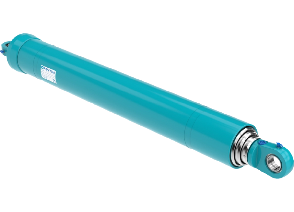
What Is a Telescopic Hydraulic Cylinder?
A telescopic hydraulic cylinder is built from several nested tubes, called stages, that extend one out of another. It gives a stroke several times longer than its collapsed length, so a long stroke fits into a short space — in tipper trucks, dump trailers, refuse bodies and lifting platforms.
Like other hydraulic cylinders it pushes with p × A — but each stage has its own area, and the thinnest stage decides the design.
- Base eye
- Oil port
- Outer tube (barrel)
- Stop ring
- Bearing and seal
- Stage 1 — widest, extends first
- Stage 2
- Last stage (plunger) — extends last
- Top eye
d1 > d2 > d3: effective stage diameters; each stage pushes with F = p × π × d² / 4.
How Does a Telescopic Hydraulic Cylinder Work?
Oil enters at the base. The widest stage moves first because it needs the least pressure; at its stop ring the pressure rises until the next stage moves, and so on to the thinnest. In a single acting unit the load pushes the stages back, usually in reverse order.
Telescopic Hydraulic Cylinder Drawing: Retracted vs Extended
Two lengths define every telescopic cylinder: the retracted (closed) length between the mounting centres, and the extended length — the retracted length plus the total stroke.
- Retracted (closed) length
- Extended length = retracted length + total stroke
- Stage 1 (largest bore — extends first)
- Last stage (smallest bore — highest pressure for the same load)
- Base tube with oil port
- Mounting eyes / trunnion
A quotation drawing states the retracted length, stroke, number of stages and outside diameter of each, mountings, oil port and working pressure — the same data we need to quote a replacement. There is no standard telescopic catalogue table: stages and bores are designed per project. Standard ranges: catalogues.
Single Acting vs Double Acting Telescopic Cylinders
| Single acting | Double acting | |
|---|---|---|
| Return stroke | Load or body weight | Oil pressure |
| Oil ports | One, at the base | Two |
| Mounting | Vertical or steep | Any, including horizontal |
| Typical use | Tipper hoists, dump trailers | Ejector blades, horizontal pushers |
Tipper hoists are almost always single acting; choose double acting when the cylinder lies horizontally or must pull.
How Many Stages? Stroke, Collapsed Length and Force per Stage
The stroke S and the collapsed length Lc decide the number of stages: each stage extends roughly its own length minus an allowance c for head, bearing and overlap.
S ≈ n × (Lc − c)Le = Lc + Sn = ⌈S / (Lc − c)⌉Fi = p × π × di² / 4
| Stages (n) | Stroke (mm) | Extended length (mm) | Stroke / collapsed length |
|---|---|---|---|
| 2 | 1,700 | 2,700 | 1.70 |
| 3 | 2,550 | 3,550 | 2.55 |
| 4 | 3,400 | 4,400 | 3.40 |
| 5 | 4,250 | 5,250 | 4.25 |
Each extra stage adds stroke, but force falls with the square of the diameter: in the example below the last stage pushes with 33 % of the first. It also has the least bearing overlap, so it is the most sensitive to side load.
Sizing a Telescopic Cylinder for a Tipper (Illustrative Calculation)
Assumptions, not a Fenitsa design: 20 t lifted (W = 196.1 kN); centre of gravity a = 2,600 mm ahead of the hinge, hg = 900 mm above it; cylinder pin b = 5,200 mm ahead of the hinge, vertical at rest, Lc = 1,300 mm; tipping to 45°; 160 bar; a sticky load that stays in the body.
- Stroke from the geometry: S = 3,905 mm, so n = ⌈3,905 / (1,300 − 150)⌉ = 4, each stage extending 976 mm.
- Start of lift: F = W × a / b = 196.1 × 2,600 / 5,200 = 98.1 kN.
- At each stage change: F = W × (a × cos φ − hg × sin φ) / r, with r the cylinder’s lever arm at body angle φ.
| Stage | Diameter (mm) | Body angle | Force needed (kN) | Pressure needed (bar) | Force at 160 bar (kN) |
|---|---|---|---|---|---|
| Stage 1 | Ø140 | 0.0° | 98.1 | 63.7 | 246.3 |
| Stage 2 | Ø120 | 10.8° | 91.0 | 80.4 | 181.0 |
| Stage 3 | Ø100 | 21.8° | 81.3 | 103.5 | 125.7 |
| Stage 4 | Ø80 | 33.1° | 68.4 | 136.0 | 80.4 |
The widest stage starts the lift at 63.7 bar, but the force needed falls more slowly than the stage area, so the pressure rises at every change: the last stage, taking over at 33.1°, needs 136.0 bar — below the 160 bar available. With a Ø70 mm last stage it would need 177.6 bar and stall. Size a telescopic cylinder on its smallest stage at the angle where it takes over.
Mounting Options
- Base eye and top eye — simplest; the pins must be parallel.
- Trunnion on the outer tube and top eye — swings in a cradle, saving height.
- Spherical bearings — tolerate chassis twist and keep bending off the stages.
Side load is the main enemy of an extended telescopic cylinder: keep the pins aligned and never tip on a side slope. Rod ends and pins: hydraulic cylinder mounts and rod ends.
Fenitsa Telescopic Range
Bores and number of stages are designed per project. We work from the stroke, collapsed length, load and mounting geometry you send; the quotation states the stage diameters, working pressure and mountings. Parts are machined, assembled, painted and inspected. Every cylinder is leakage-tested, and Fenitsa provides 10 years of service and spare-parts support. See also dump truck cylinders, the FDH series and custom hydraulic cylinders.
Telescopic Hydraulic Cylinder – FAQ
What is the difference between a telescopic and a normal hydraulic cylinder?
A normal cylinder’s stroke is shorter than its collapsed length; a telescopic cylinder’s stroke can be several times its collapsed length. The cost is lower force on the thinner stages and less tolerance of side load.
How is telescopic cylinder force calculated?
Separately for each stage: F = p × π × d² / 4 with that stage’s effective diameter. At 160 bar a Ø140 mm stage pushes 246.3 kN and a Ø80 mm stage 80.4 kN.
How many stages do I need?
Divide the required stroke by the stroke one stage gives from your collapsed length and round up: n = S / (Lc − c). More stages give more stroke but a weaker last stage.
Why does a telescopic cylinder extend in steps?
Each stage needs a different pressure, so they move one after another, widest first. Speed also rises at each step, since the same flow fills a smaller area.
What pressure does a telescopic cylinder work at?
It is chosen per project with the stage diameters and confirmed in the quotation; the examples here use 160 bar, the working pressure of Fenitsa’s FDH series.
Send Us Your Cylinder Data
Bore, rod, stroke, working pressure, mountings and quantity — or a drawing or photo of the cylinder you want to replace. Our engineers reply with a technical proposal and a quotation. info@fenitsa.com.
Related Pages
- Dump Truck and Dump Trailer Cylinders — hoist layouts and stage selection.
- Single Acting Hydraulic Cylinders — types and force table.
- How to Measure a Hydraulic Cylinder — dimensions for a replacement.

