

 Türkçe
 Русский
 Español
 العربية
Long Stroke Hydraulic Cylinders
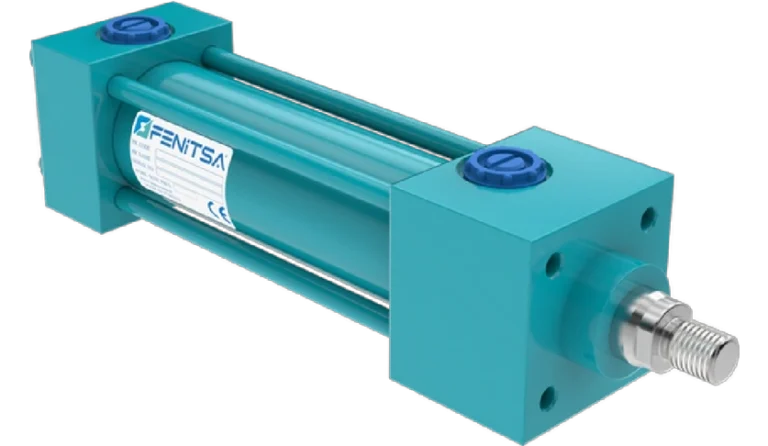
A long stroke hydraulic cylinder is one whose stroke is long compared with its rod diameter, so that rod buckling — not bore or pressure — sets the design. Fenitsa FDH cylinders are built with strokes up to 5,000 mm on Ø40–Ø200 mm bores, with rods from Ø25 to Ø125 mm chosen for the pushing load and the mounting.
Below: where “long” begins for each bore of our hydraulic cylinders, how the mounting changes the buckling length, Euler examples up to 5,000 mm, rod finish and installation.
What Counts as a Long Stroke?
There is no formal definition. A practical one: a stroke is long when the rod can no longer take the cylinder’s full push force with a safe margin. Below that point bore and pressure decide the size; above it, the rod and the mounting do.
| Bore | Push at 160 bar (t) | Thinner rod | Thicker rod |
|---|---|---|---|
| Ø40 mm | 2.1 | Ø25: 751 mm | Ø28: 943 mm |
| Ø50 mm | 3.2 | Ø28: 754 mm | Ø36: 1,247 mm |
| Ø63 mm | 5.1 | Ø36: 989 mm | Ø45: 1,546 mm |
| Ø80 mm | 8.2 | Ø45: 1,217 mm | Ø56: 1,885 mm |
| Ø100 mm | 12.8 | Ø56: 1,508 mm | Ø70: 2,357 mm |
| Ø125 mm | 20.0 | Ø70: 1,885 mm | Ø90: 3,117 mm |
| Ø160 mm | 32.8 | Ø90: 2,435 mm | Ø100: 3,006 mm |
| Ø200 mm | 51.3 | Ø110: 2,910 mm | Ø125: 3,757 mm |
The limit lies at a free length of about 15–25 times the bore. Pinned at both ends, the free length is roughly twice the stroke plus the dead length, so buckling can govern from strokes below 7–12 times the bore. The 5,000 mm maximum is 25 times a Ø200 mm bore.
Buckling and Rod Diameter Selection
Fk = π² × E × I / Lk²I = π × d⁴ / 64 · E = 210,000 N/mm²Lk = K × free length · permissible push = Fk / 3.5An extended rod works as a column. The check here treats the rod alone as the column over the full free length — conservative, because the barrel is much stiffer than the rod — with a safety factor of 3.5, a common engineering practice. For short, thick rods Euler overstates the capacity and the rod’s compressive stress governs instead.
The mounting factor K turns the free length into the buckling length. General Euler cases with the matching Fenitsa mounting codes:
| Cylinder mounting | Rod end | Euler case | Factor K | Free length measured |
|---|---|---|---|---|
| Front flange (FFM) or foot (FMM) | Free, not guided | Fixed – free | 2.0 | Mounting face to rod end |
| Rear clevis (RSM, RHM) | Rod clevis or spherical eye (FSM, FRM) | Pinned – pinned | 1.0 | Pin to pin |
| Front flange (FFM) | Pinned and guided | Fixed – pinned | 0.7 | Flange face to rod pin |
| Front flange (FFM) | Fixed to a rigidly guided platen | Fixed – fixed | 0.5 | Flange face to platen |
Trunnion mountings (CTM) fall between these cases and are checked individually. The mounting matters as much as the rod: going from a free rod end (K = 2) to a guided one (K = 0.7) multiplies the permissible load by 8.2.
Worked examples. Four cylinders with the thicker catalogue rod, checked against their full 160 bar push. A = front flange, pinned and guided rod end (free length = stroke + dead length); B = pinned at both ends (free length = 2 × stroke + dead length). Dead length taken as 400 mm for illustration.| Stroke | Bore / rod | Full push at 160 bar (t) | A: buckling length (mm) | A: permissible push (t) | A: result | B: buckling length (mm) | B: permissible push (t) | B: result |
|---|---|---|---|---|---|---|---|---|
| 1,000 mm | Ø63 / Ø45 mm | 5.1 | 980 | 12.7 | OK | 2,400 | 2.1 | Too slender |
| 2,000 mm | Ø100 / Ø70 mm | 12.8 | 1,680 | 25.2 | OK | 4,400 | 3.7 | Too slender |
| 3,000 mm | Ø160 / Ø100 mm | 32.8 | 2,380 | 52.3 | OK | 6,400 | 7.2 | Too slender |
| 5,000 mm | Ø200 / Ø125 mm | 51.3 | 3,780 | 50.6 | Too slender | 10,400 | 6.7 | Too slender |
With mounting A the first three cylinders carry their full push. At 5,000 mm the Ø200 / Ø125 mm cylinder is allowed 50.6 t against 51.3 t: set the relief valve to about 158 bar, or fix the rod end to a rigidly guided platen (K = 0.5) for 99.3 t.
With mounting B every example fails: pinned at both ends, the same cylinders may push only 2.1 to 7.2 t. Long pushing strokes are therefore flange-mounted with a guided load — or the cylinder lifts by pulling, like a gate hanging from the rod, so the rod works in tension and cannot buckle.
Guiding and Stop Tubes
General engineering practice for long, extended cylinders.
- A cylinder is not a guideSide loads are carried by two short bearing zones — the rod bearing in the head and the piston wear rings. At full extension they are closest together, so a small side load becomes a high bearing pressure.
- Guide the loadSlides, columns or a guided platen take the side loads; the cylinder only pushes and pulls, and the mounting factor drops. Spherical rod and clevis bearings (FRM, RHM) absorb small misalignments.
- Stop tubeA spacer on the rod between piston and head keeps the two bearing zones apart at full extension, at the cost of a longer body. Stop tubes can be specified on request; side load and mounting decide whether one is needed.
Straightness and Rod Finish
Fenitsa rods are Ck45 steel, hard chrome plated to at least 20 µm and ground to f7 tolerance; hardened-and-chromed (HR) and stainless (SS) rods are options. Barrels are honed St52BK+S tube. On a long cylinder a rod that is not straight adds a bending moment to the buckling load, and the chrome is the running surface for the rod seal and wiper over the whole stroke.
Long horizontal rods also carry their own weight (steel, 7.85 kg/dm³):
| Rod | Weight per metre (kg) | Weight of 5,000 mm (kg) |
|---|---|---|
| Ø56 mm | 19.3 | 97 |
| Ø70 mm | 30.2 | 151 |
| Ø90 mm | 49.9 | 250 |
| Ø110 mm | 74.6 | 373 |
| Ø125 mm | 96.3 | 482 |
Transport and Installation of Long Cylinders
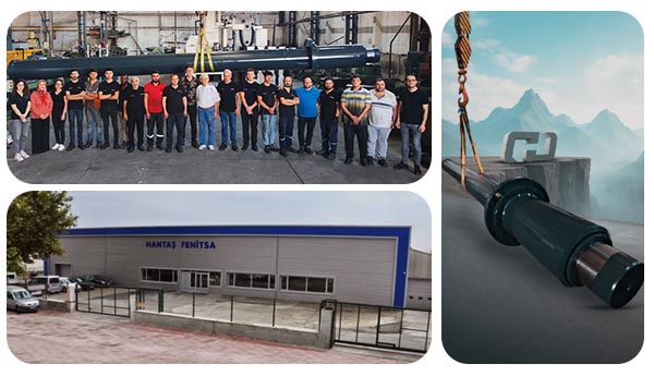
- Ship retracted and supportedRod retracted, barrel supported at several points, never resting on the rod.
- Lift by the bodyTwo slings on the barrel or mountings; lifting at one end bends a long cylinder.
- Protect the chromeA scratch on the rod becomes a leak path at the seal.
- Align both mountingsParallel pins at both ends; misalignment turns push force into bending.
- Fill and bleedCheck the tank volume first (see the FAQ), bleed at the highest point and run the first strokes slowly.
Every Fenitsa cylinder passes an internal and external leakage test before it leaves the plant.
Applications
Dam and sluice gates
Long strokes, load holding and cylinders that must work after months standing still. Dam gate cylinders
Presses with long daylight
Compactors, balers and deep presses; the guided platen keeps the buckling length short. Press cylinders
Heavy lifting platforms
Lifting tables and stages, often with several synchronised cylinders. Heavy-load cylinders
Check load and stroke with our hydraulic cylinder sizing guide. Above 3,000 mm stroke the FDH series is the standard route; see also tie-rod hydraulic cylinders.
Send Us Your Cylinder Data
Bore, rod, stroke, working pressure, mountings and quantity — or a drawing or photo of the cylinder you want to replace. Our engineers reply with a technical proposal and a quotation. info@fenitsa.com.
Long Stroke Hydraulic Cylinders – FAQ
Short answers from our engineers.
What is the maximum stroke of a hydraulic cylinder?
There is no universal limit; it depends on the rod, the mounting and the pushing load. Fenitsa FDH cylinders are built with strokes up to 5,000 mm, and the KHS and THS series are listed with strokes up to 3,000 mm. Longer pushing strokes need a thicker rod or a guided load.
How do you stop a long cylinder rod from buckling?
Shorten the buckling length or stiffen the rod. Guide the rod end and flange-mount the cylinder, choose the thicker rod option or the next bore size, lower the relief pressure to the force you really need, or arrange the cylinder to lift by pulling so the rod works in tension.
Do long stroke cylinders need a stop tube?
Not always. It helps when a long, extended cylinder carries side loads; with an externally guided load it is often unnecessary. Stop tubes can be specified on request.
Can a long stroke cylinder be mounted horizontally?
Yes, with a guided rod end or a support. A Ø125 mm rod weighs 96.3 kg per metre; extended several metres unsupported, it sags and loads the rod bearing.
How much oil does a 5,000 mm stroke cylinder need?
A Ø200 mm bore needs 157.1 L to extend 5,000 mm; with a Ø125 mm rod the rod side holds 95.7 L. The tank and pump must handle that volume and the 61.4 L difference between the two chambers.
How fast can a long stroke cylinder move?
The standard series is limited to a piston speed of 0.5 m/s, so a 5,000 mm stroke takes at least 10 seconds. Plan the pump flow for the speed you need: at 0.5 m/s a Ø200 mm bore takes 942 L/min.
Related Pages
Hydraulic Cylinder Sizes
Bores, rods, strokes and the bore-to-tons chart.
Hydraulic Cylinder Sizing
Selecting bore, rod, stroke and mountings step by step.
Hydraulic Cylinders for Dam Gate Systems
Long-stroke hoist cylinders for gates.
Industrial Hydraulic Cylinders for Heavy Loads
Multi-cylinder lifting and load holding.