

 Türkçe
 Русский
 Español
 العربية
Heavy Duty Hydraulic Cylinders for Heavy Loads
A heavy duty hydraulic cylinder is sized and built for high, sustained or shock loads: a bore large enough for the force at the working pressure, a rod thick enough not to buckle, and mountings that keep side load off the rod. Fenitsa builds them from Ø40 to Ø200 mm bore for 160 bar, with a 250 bar option.
A Ø200 mm cylinder gives 51.3 tonnes of theoretical push at 160 bar and 80.1 tonnes at 250 bar. This page lists the specifications of our heavy-duty hydraulic cylinders for presses, steel mills, dam gates, mining and lifting systems, shows how to check the rod for buckling and explains how to share a load between several cylinders.
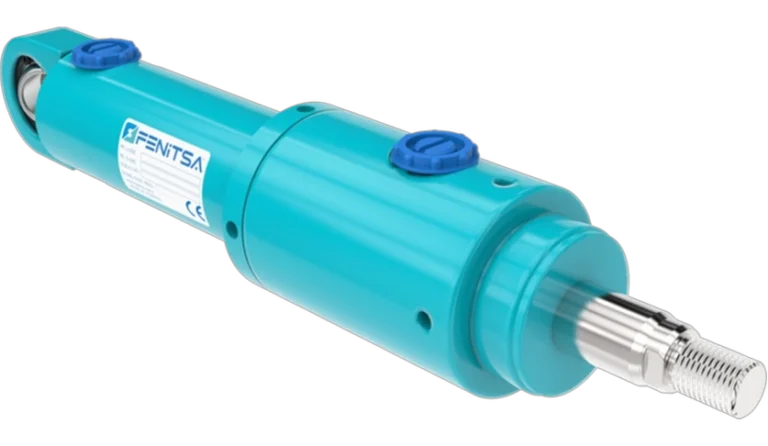
Heavy Duty Hydraulic Cylinder Specifications
Published values of the FDH catalogue series and the KHS heavy-duty range.
- Working pressure160 bar (16 MPa)
- Test pressure240 bar (24 MPa)
- Optional pressure250 bar (25 MPa)
- BoresØ40–Ø200 mm
- RodsØ25–Ø125 mm
- Maximum stroke5,000 mm
- Max piston speed0.5 m/s
- Oil temperature−20 to +80 °C
| Bore | Rod options (mm) | Rod-end thread | Piston area (cm²) |
|---|---|---|---|
| Ø40 mm | Ø25 / Ø28 | M16×1.5 | 12.6 |
| Ø50 mm | Ø28 / Ø30 / Ø36 | M20×1.5 | 19.6 |
| Ø63 mm | Ø36 / Ø45 | M27×2 | 31.2 |
| Ø80 mm | Ø45 / Ø56 | M33×2 | 50.3 |
| Ø100 mm | Ø56 / Ø70 | M42×2 | 78.5 |
| Ø125 mm | Ø70 / Ø90 | M48×2 | 122.7 |
| Ø160 mm | Ø90 / Ø100 | M64×3 | 201.1 |
| Ø200 mm | Ø110 / Ø125 | M80×3 | 314.2 |
Load and Buckling Check
A slender pushing rod can buckle well before the cylinder reaches its pressure limit.
Fk = π² × E × I / Lk²I = π × d⁴ / 64Lk = K × LFperm = Fk / SE is 210,000 N/mm² for steel, d the rod diameter, L the free length between the mounting points at full extension and K the mounting factor below. A safety factor S = 3.5 against Euler buckling is common engineering practice. Treating the rod as the whole column is conservative, because the tube is stiffer than the rod.
| Euler case | Cylinder mounting | Rod end | Factor K |
|---|---|---|---|
| Case 1 | Fixed: front or rear flange, foot | Free and unguided | 2.0 |
| Case 2 | Pivot: rear clevis or trunnion | Pivot, guided (rod eye) | 1.0 |
| Case 3 | Fixed: flange | Pivot, guided | 0.7 |
| Case 4 | Fixed: flange | Fixed and guided | 0.5 |
Real mountings sit between the ideal cases; when in doubt, use the larger factor.
Worked example. A Ø100 mm cylinder lifts at 160 bar with a rear clevis and rod eye (case 2, K = 1). Pin-to-pin length at full extension: L = 2,000 mm. Push force: F = 125.7 kN (12.8 t).Ø56 mm rod: I = 482,750 mm⁴, Fk = 250.1 kN, permissible Fk / 3.5 = 71.5 kN — below the 125.7 kN push force, so the rod is at risk of buckling.Ø70 mm rod: I = 1,178,588 mm⁴, Fk = 610.7 kN, permissible Fk / 3.5 = 174.5 kN — above 125.7 kN, so the Ø70 mm rod option is the right choice. With this rod, the longest pin-to-pin length at full force is √(π² × E × I / (S × F)) = 2,357 mm.The check is one step of hydraulic cylinder sizing; the force calculator gives the push force for any bore.
Lifting Capacity with One, Two or Four Cylinders
Theoretical push force in metric tonnes at 160 bar working pressure, and one cylinder at the 250 bar option.
| Bore | 1 cylinder | 2 cylinders | 4 cylinders | 1 cylinder at 250 bar |
|---|---|---|---|---|
| Ø80 mm | 8.2 | 16.4 | 32.8 | 12.8 |
| Ø100 mm | 12.8 | 25.6 | 51.3 | 20.0 |
| Ø125 mm | 20.0 | 40.0 | 80.1 | 31.3 |
| Ø160 mm | 32.8 | 65.6 | 131.2 | 51.3 |
| Ø200 mm | 51.3 | 102.5 | 205.0 | 80.1 |
Multiply by the number of cylinders only if the load is shared evenly — and it rarely is. The centre of gravity, frame stiffness and hose lengths make one cylinder carry more than its share, so size each cylinder for the highest load it can see, not the average.
Moving and Holding Heavy Loads
Flow dividers
Split the pump flow so several cylinders extend together. Simple, moderately accurate; the error grows with stroke.
Rigid linking
A stiff frame or platen forces the cylinders to move together. The frame must carry the uneven loads.
Position control
Sensors and proportional valves correct each cylinder continuously; the most accurate method.
Load holding
A pilot-operated check or counterbalance valve on each cylinder holds the load if a hose fails. Mount it on the cylinder, not at the power unit.
Mechanical locks
For long holding or people under the load, add lock nuts, props or stops as a second safety layer.
Where Heavy Duty Cylinders Are Used
Presses
Forming, baling and compacting presses where the bore sets the tonnage. Press cylinders.
Dam and sluice gates
Cylinders that raise gates and hold them against water pressure. Dam gate cylinders.
Steel mills and heavy industry
Handling and cutting equipment near heat and scale; special seals cover up to +200 °C.
Mining
Cylinders for dusty, high-impact work. Mining cylinders.
Marine
Hatch covers, cranes and ramps in salt-water environments. Marine cylinders.
Lifting and jacking
Platforms, lifting frames and jacking systems with several cylinders.
Send Us Your Cylinder Data
Bore, rod, stroke, working pressure, mountings and quantity — or a drawing or photo of the cylinder you want to replace. Our engineers reply with a technical proposal and a quotation. info@fenitsa.com.
Heavy Duty Hydraulic Cylinders – FAQ
Short answers from our engineers.
How much can a hydraulic cylinder lift?
Theoretical lifting force is pressure × piston area. A Ø200 mm cylinder at 160 bar lifts about 51.3 tonnes, and about 80.1 tonnes at 250 bar. Real capacity is lower: allow for seal friction, pressure losses and uneven load sharing between cylinders.
How do you check a hydraulic cylinder rod for buckling?
Treat the rod as a column: F_k = π² × E × I / L_k², with I = π × d⁴ / 64 and L_k = mounting factor × free length. Divide F_k by a safety factor, commonly 3.5, and compare it with the push force; if it is lower, use a thicker rod or a shorter buckling length.
What pressure do Fenitsa heavy duty cylinders work at?
160 bar (16 MPa) working pressure and 240 bar (24 MPa) test pressure, with a 250 bar (25 MPa) option. These are the published values of the FDH catalogue series; for KHS cylinders the rating is confirmed in the quotation.
How do I keep several lifting cylinders level?
With flow dividers, a rigid linking frame or electronic position control, depending on the accuracy required. A position sensor on each cylinder gives the most accurate result on large platforms.
What stops a heavy load from dropping if a hose bursts?
A load-holding valve — a pilot-operated check valve or a counterbalance valve — mounted directly on each cylinder. It locks the oil in the cylinder when the supply pressure is lost. For long holding periods, add a mechanical lock or prop as a second safety layer.
Can you build hydraulic cylinders with bores larger than Ø200 mm?
Yes. Larger bores are built to order. Send the load, stroke, working pressure and mounting arrangement, and Fenitsa engineers will propose a bore and rod for the load case.
Related Pages
Hydraulic Press Cylinders
Tonnage table Ø40–Ø200 mm at 160 and 250 bar.
KHS Type Hydraulic Cylinders
Heavy-duty cylinders for mobile equipment.
FDH Type Hydraulic Cylinders
Catalogue series, 160 bar, strokes to 5,000 mm.
Long Stroke Hydraulic Cylinders
Strokes up to 5,000 mm and how to keep them straight.
Hydraulic Cylinder Sizing
Bore, rod and stroke step by step.