

 Türkçe
 Русский
 Español
 العربية
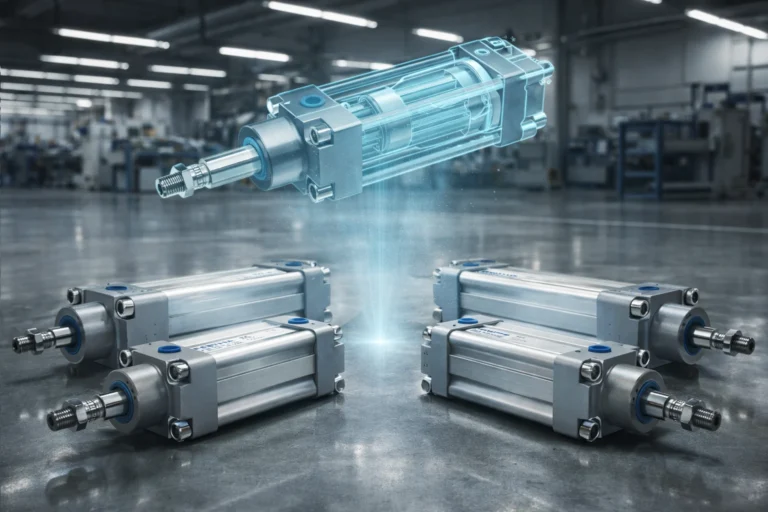
Double Acting Pneumatic Cylinders
A double acting pneumatic cylinder has an air port at each end, so compressed air drives the piston both out and back. It does work in both directions, its speed can be set separately for each stroke, and the stroke length is not limited by a return spring.
Every Fenitsa standard pneumatic cylinder is double acting: ISO 15552 FMY and CETOP PAG, PNS, PMB and FOC series from Ø32 to Ø320 mm, working at 1.5–10 bar, with double rod, tandem and two-position tandem versions.
How a Double Acting Air Cylinder Works
Air supplied to port A, in the rear cap, acts on the full piston area and pushes the rod out while the air in front of the piston escapes through port B. Reversing the valve feeds port B: the air now acts on the annulus around the rod and pulls the piston back while port A exhausts.
Because the rod occupies part of the front face, the pull force is always a little lower than the push force. The difference depends on the rod-to-bore ratio — from about 16 % on a Ø40 mm cylinder with a Ø16 mm rod to about 4 % on the large bores — and it matters when the return stroke has to lift or drag a load.
- Rear cap (cap end)
- Rear clevis mounting
- Port A — cap end (full bore side)
- Barrel (cylinder tube)
- Tie rods and nuts
- Piston
- Piston seal
- Wear (guide) rings
- Piston rod
- Front head (gland)
- Rod bearing (guide bush)
- Rod seal
- Wiper (scraper)
- Port B — rod end (annulus side)
- Cushioning spear and adjusting screw
- Static O-rings
- Rod eye
Cap-side chamber — pressure acts on the full piston area · Rod-side chamber — pressure acts on the annulus area
Push and Pull Force at 6 bar (Ø32–Ø320 mm)
Theoretical values; allow roughly 10 % for seal friction.
| Bore | Rod | Push (N) | Pull (N) | Push (lbf) | Pull (lbf) |
|---|---|---|---|---|---|
| Ø32 mm | Ø12 mm | 483 | 415 | 108 | 93 |
| Ø40 mm | Ø16 mm | 754 | 633 | 170 | 142 |
| Ø50 mm | Ø20 mm | 1,178 | 990 | 265 | 222 |
| Ø63 mm | Ø20 mm | 1,870 | 1,682 | 420 | 378 |
| Ø80 mm | Ø25 mm | 3,016 | 2,721 | 678 | 612 |
| Ø100 mm | Ø25 mm | 4,712 | 4,418 | 1,059 | 993 |
| Ø125 mm | Ø32 mm | 7,363 | 6,881 | 1,655 | 1,547 |
| Ø160 mm | Ø40 mm | 12,064 | 11,310 | 2,712 | 2,543 |
| Ø200 mm | Ø40 mm | 18,850 | 18,096 | 4,238 | 4,068 |
| Ø250 mm | Ø50 mm | 29,452 | 28,274 | 6,621 | 6,356 |
| Ø320 mm | Ø63 mm | 48,255 | 46,385 | 10,848 | 10,428 |
Formula: push F = p × A; pull F = p × (A − a), where A is the piston area and a the rod area. The Fenitsa pneumatic catalogue lists the same forces in kilograms using 1 kg ≈ 10 N — for example 471 kg push and 441 kg pull for Ø100 mm, or 4,823 kg and 4,638 kg for Ø320 mm.
For dynamic motion size the bore so that the load needs no more than 50–70 % of the theoretical force. The air cylinder calculator gives push and pull force for any pressure in bar or psi.
Sizing Example: Choosing the Bore
A pusher has to move cartons with a force of 800 N, and the factory network supplies 6 bar. For a moving load, plan on using no more than about 60 % of the theoretical force, so the cylinder should deliver 800 / 0.6 ≈ 1,333 N.
Required piston area: A = F / p = 1,333 N / 0.6 N/mm² ≈ 2,222 mm², which corresponds to a bore of √(4A / π) ≈ 53 mm. The next standard bore is Ø63 mm, giving about 1,870 N push and 1,682 N pull at 6 bar — enough margin in both directions. Ø50 mm (1,178 N) would be too small.
Fenitsa Double Acting Series
| Series | Standard | Bores | Notes |
|---|---|---|---|
| FMY | ISO 15552 | Ø32–Ø100 and Ø125–Ø320 mm | Magnetic piston, adjustable cushioning |
| PAG / PAGY | CETOP RP 43P | Ø32–Ø100 mm | PAG cushioned, PAGY without cushioning |
| PNS / PNSY | CETOP RP 43P and RP 53P | Ø32–Ø100 and Ø125–Ø320 mm | PNS cushioned, PNSY without cushioning |
| PMB | CETOP RP 53P | — | Magnetic piston, cushioned |
| FOC / FOCY | CETOP RP 43P | — | Special series |
| FNC / FMC | Compact | — | Compact body; FMC with magnetic piston |
Each series is also available as a double rod cylinder (code C), a tandem cylinder (code T) that doubles the force from the same bore, and a two-position tandem (code D) with two strokes in one unit. See tandem cylinders and double rod cylinders.
Cushioning and Magnetic Piston
Adjustable end cushioning slows the piston during the last millimetres of travel: a cushion sleeve enters a seal in the end cap, traps a small volume of air and lets it out through an adjustable needle. It protects the cylinder and the machine from impact at the end of each stroke, and it is set once on the machine with a screwdriver.
FMY, PMB and FMC cylinders have a magnetic piston. Position sensors mounted on the outside of the barrel detect the magnet, so the control system knows when the cylinder has reached its end positions without mechanical limit switches.
ISO 15552 Key Dimensions (FMY, Ø32–Ø100)
From the Fenitsa pneumatic catalogue.
| Bore | Rod | Rod thread | Port | Mounting bolt spacing (TG) | Body length without stroke |
|---|---|---|---|---|---|
| Ø32 | Ø12 | M10×1.25 | G1/8 | 32.5 | 94 |
| Ø40 | Ø16 | M12×1.25 | G1/4 | 38 | 105 |
| Ø50 | Ø20 | M16×1.5 | G1/4 | 46.5 | 106 |
| Ø63 | Ø20 | M16×1.5 | G3/8 | 56.5 | 121 |
| Ø80 | Ø25 | M20×1.5 | G3/8 | 72 | 128 |
| Ø100 | Ø25 | M20×1.5 | G1/2 | 89 | 138 |
Because ISO 15552 fixes these interface dimensions, an FMY cylinder fits the same mountings, rod ends and space as other ISO 15552 cylinders of the same bore — useful when replacing a cylinder on an existing machine. Mountings (rear clevis, flange, foot, trunnion, rod clevis and spherical rod end) are available from Ø32 to Ø320 mm.
Speed Control
Cylinder speed is set with flow control valves on the exhaust side (meter-out), which gives smoother motion than restricting the supply. The achievable speed depends on the valve and hose size, the load and the pressure, so it is best confirmed on the machine. For very slow, even motion, a pneumatic–hydraulic speed-adjusting tank is available as a special accessory.
Applications
Packaging and food lines
Pushers, diverters, gates and cutters. Food-grade options.
Assembly and handling
Pressing, positioning and transferring parts in automation cells.
Textile and printing machines
Fast, repeatable strokes with adjustable cushioning.
Large-bore work
Ø125–Ø320 mm cylinders deliver up to about 48 kN at 6 bar for doors, lifts and forming.
Single or Double Acting?
Choose double acting when the return stroke has to do work, when the stroke is long or when the speed must be controlled in both directions. A single acting (spring return) cylinder is simpler and uses about half the air, but only for short strokes and light return loads.
Send Us Your Cylinder Data
Bore, rod, stroke, working pressure, mountings and quantity — or a drawing or photo of the cylinder you want to replace. Our engineers reply with a technical proposal and a quotation. info@fenitsa.com.
Double Acting Pneumatic Cylinder – FAQ
Short answers from our engineers.
What is a double acting pneumatic cylinder?
An air cylinder with a port at each end. Compressed air drives the piston out through one port and back through the other, so the cylinder does work in both directions.
Why is the pull force lower than the push force?
On the return stroke the air acts on the annulus — the piston area minus the rod area. For a Ø63 mm cylinder with a Ø20 mm rod at 6 bar that is about 1,682 N instead of 1,870 N.
What does the “Y” in PAGY or PNSY mean?
In the Fenitsa catalogue the Y versions are the plain double acting cylinders; the versions without Y (PAG, PNS, FOC …) have adjustable end cushioning.
Which valve controls a double acting cylinder?
A 5/2 valve for simple back-and-forth motion, or a 5/3 valve when the cylinder must stop or hold in mid-stroke. The Fenitsa catalogue lists 1/4" 5/2 and 5/3 valves with manual, lever, pedal and pilot actuation.
What pressure do Fenitsa pneumatic cylinders work at?
From 1.5 to 10 bar with filtered, lubricated air. Force tables are usually quoted at 6 bar, the typical factory network pressure.
Can you make double acting cylinders with a special stroke?
Yes. Standard strokes run from 50 to 500 mm, and other strokes are produced to order.
Related Pages
ISO 15552 Cylinder FMY (Ø125–Ø320)
Large-bore ISO cylinders up to about 48 kN at 6 bar.
CETOP RP 43P Cylinder PAG-PAGY
Aluminium-body CETOP cylinders Ø32–Ø100 mm.
Double Acting Hydraulic Cylinders
Push and pull with oil at 160 bar.
Single Acting Pneumatic Cylinders
Spring-return cylinders and the net force formula.