

 Türkçe
 Русский
 Español
 العربية
Double Acting Hydraulic Cylinders
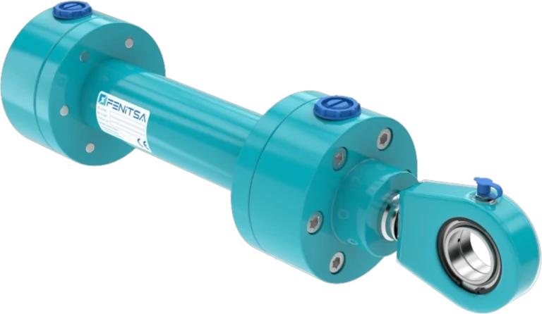
A double acting hydraulic cylinder has an oil port at each end, so pressure drives the piston both out and back. It pushes with the full piston area, pulls with the smaller annulus around the rod, and its force and speed can be controlled in both directions. Most industrial and mobile hydraulic cylinders are double acting.
Fenitsa builds double acting hydraulic cylinders in the FDH standard series — Ø40–Ø200 mm bore, Ø25–Ø125 mm rods, 160 bar (250 bar option), strokes to 5,000 mm — and to customer drawings. Below: push and pull force for every catalogue bore and rod, flow and speed, and when to choose double acting.
What Is a Double Acting Hydraulic Cylinder?
Inside the barrel, the piston and its seal divide the oil into two chambers: the cap-end chamber behind the piston and the rod-end chamber around the rod. Each has its own port, so each can be pressurised or drained. The rod leaves through the front head, where the guide bush carries it, the rod seal keeps oil in and the wiper keeps dirt out.
Because both chambers are full of oil and sealed, the cylinder is stiff in both directions: with both ports blocked it holds its load against push and pull, limited only by leakage across the piston seal and in the valve. Every Fenitsa cylinder is tested for internal and external leakage.
How Does a Double Acting Hydraulic Cylinder Work?
Port A at the cap end and port B at the rod end are connected to a four-way directional valve. Flow into port A pushes the piston out while the oil in front of it leaves through port B to tank. Switching the valve feeds port B: the oil acts on the annulus and pulls the piston back while port A drains. In the centre position of a 4/3 valve the ports can be blocked to hold the cylinder.
The area ratio φ = A / (A − a) links the two directions. With the same flow the rod retracts φ times faster than it extends; at the same pressure it pulls with 1/φ of its push force. The oil leaving port A during retraction is φ times the pump flow — size the return line for it.
- Rear cap (cap end)
- Rear clevis mounting
- Port A — cap end (full bore side)
- Barrel (honed cylinder tube)
- Tie rods and nuts
- Piston
- Piston seal
- Wear (guide) rings
- Piston rod (hard chrome plated)
- Front head (gland)
- Rod bearing (guide bush)
- Rod seal
- Wiper (scraper)
- Port B — rod end (annulus side)
- Cushioning spear and adjusting screw
- Static O-rings
- Rod eye
Cap-side chamber — pressure acts on the full piston area · Rod-side chamber — pressure acts on the annulus area
Push vs Pull Force: The Annulus Area Formula
Fpush = p × π × D² / 4Fpull = p × π × (D² − d²) / 4φ = D² / (D² − d²)Worked example — Ø80 mm bore, Ø45 mm rod, 160 bar. Piston area = π × 80² / 4 = 5,027 mm²; annulus = π × (80² − 45²) / 4 = 3,436 mm². Push = 160 × 0.1 × 5,027 = 80,425 N = 80.4 kN ≈ 8.20 t. Pull = 160 × 0.1 × 3,436 = 54,978 N = 55.0 kN ≈ 5.61 t. φ = 1.46, so the rod retracts 1.46 times faster than it extends with the same flow.
A thicker rod lowers the pull force and raises φ, but it resists buckling better on long push strokes. That is why the catalogue offers two or three rods per bore.
Push and Pull Force Table at 160 bar (Ø40–Ø200 mm)
Every FDH bore with each catalogue rod option. Theoretical values, before friction.
| Bore × rod (mm) | Push (kN) | Push (t) | Pull (kN) | Pull (t) | Area ratio φ |
|---|---|---|---|---|---|
| Ø40 × Ø25 | 20.1 | 2.05 | 12.3 | 1.25 | 1.64 |
| Ø40 × Ø28 | 20.1 | 2.05 | 10.3 | 1.05 | 1.96 |
| Ø50 × Ø28 | 31.4 | 3.20 | 21.6 | 2.20 | 1.46 |
| Ø50 × Ø30 | 31.4 | 3.20 | 20.1 | 2.05 | 1.56 |
| Ø50 × Ø36 | 31.4 | 3.20 | 15.1 | 1.54 | 2.08 |
| Ø63 × Ø36 | 49.9 | 5.09 | 33.6 | 3.43 | 1.48 |
| Ø63 × Ø45 | 49.9 | 5.09 | 24.4 | 2.49 | 2.04 |
| Ø80 × Ø45 | 80.4 | 8.20 | 55.0 | 5.61 | 1.46 |
| Ø80 × Ø56 | 80.4 | 8.20 | 41.0 | 4.18 | 1.96 |
| Ø100 × Ø56 | 125.7 | 12.81 | 86.3 | 8.80 | 1.46 |
| Ø100 × Ø70 | 125.7 | 12.81 | 64.1 | 6.54 | 1.96 |
| Ø125 × Ø70 | 196.3 | 20.02 | 134.8 | 13.74 | 1.46 |
| Ø125 × Ø90 | 196.3 | 20.02 | 94.6 | 9.64 | 2.08 |
| Ø160 × Ø90 | 321.7 | 32.80 | 219.9 | 22.42 | 1.46 |
| Ø160 × Ø100 | 321.7 | 32.80 | 196.0 | 19.99 | 1.64 |
| Ø200 × Ø110 | 502.7 | 51.26 | 350.6 | 35.75 | 1.43 |
| Ø200 × Ø125 | 502.7 | 51.26 | 306.3 | 31.23 | 1.64 |
Rod-end threads run from M16×1.5 on Ø40 mm to M80×3 on Ø200 mm. For the optional 250 bar, multiply every force by 250 / 160 = 1.5625. Other bores, rods or pressures: hydraulic cylinder force calculator.
Types of Double Acting Hydraulic Cylinders
Tie-rod
Heads clamped to the barrel by tie rods, easy to strip and reseal. Fenitsa’s tie-rod range covers Ø40–Ø200 mm at 160 bar. See tie-rod cylinders.
Welded
Cap welded to the barrel, compact for mobile machines — see welded cylinders. Fenitsa’s THS range is welded and compact; KHS is heavy duty. Both: Ø40–Ø200 mm, strokes to 3,000 mm.
Double acting telescopic
Nested stages powered out and back, for long strokes where gravity cannot return the load. Designed per project — see telescopic cylinders.
Double rod
A rod through both heads gives equal areas, so force and speed match in both directions. An FDH option.
Tandem
Two pistons in series on one rod add a second pressurised area, raising the force from the same bore. An FDH option.
Adjustable stroke
An adjustable stop limits the working stroke. An FDH option.
Cushioning and Speed
End cushioning slows the piston over the last part of the stroke: a spear enters a bore in the head, the trapped oil escapes through an adjustable needle valve, and the pressure it builds brakes the piston. Specify it when the piston reaches the end of stroke at speed or with a heavy mass; cushioning is agreed per order and confirmed in the quotation.
Speed follows from flow: v = Q / A extending and v = Q / (A − a) retracting. The FDH catalogue limit is 0.5 m/s. The table uses the thinner rod of each bore.
| Bore × rod (mm) | Q for 0.1 m/s (L/min) | Q for 0.5 m/s (L/min) | Retraction speed with the 0.1 m/s flow (mm/s) |
|---|---|---|---|
| Ø40 × Ø25 | 7.5 | 37.7 | 164 |
| Ø50 × Ø28 | 11.8 | 58.9 | 146 |
| Ø63 × Ø36 | 18.7 | 93.5 | 148 |
| Ø80 × Ø45 | 30.2 | 150.8 | 146 |
| Ø100 × Ø56 | 47.1 | 235.6 | 146 |
| Ø125 × Ø70 | 73.6 | 368.2 | 146 |
| Ø160 × Ø90 | 120.6 | 603.2 | 146 |
| Ø200 × Ø110 | 188.5 | 942.5 | 143 |
Hydraulic power is P [kW] = p [bar] × Q [L/min] / 600: a Ø80 mm cylinder extending at 0.1 m/s needs 30.2 L/min, or 8.0 kW at 160 bar.
Single vs Double Acting: When to Choose Double Acting
Six cases in which a single acting cylinder will not do the job.
- The return stroke has to do workPulling a load, closing a gate or retracting against friction.
- Gravity cannot return the rodThe cylinder is horizontal, inclined the wrong way or upside down.
- Speed must be controlled both waysReturn speed must be metered as precisely as the working stroke.
- The load must be held both waysBooms, arms and gates that must not move with the valve closed.
- The rod side must stay sealedDusty or washed-down areas, where a breather would draw in dirt.
- The stroke is long and nothing pushes backA return spring is impractical and the load cannot return the rod.
If none of these applies, a single acting hydraulic cylinder is simpler — one hose and a smaller valve. The comparison table is on that page.
Applications
Construction machinery
Boom, arm and bucket cylinders. Construction cylinders.
Agricultural machinery
Loaders, implements and steering. Agricultural cylinders.
Presses
Pressing stroke plus a powered return. Press cylinders.
Injection moulding
Clamping and ejector motions. Injection moulding cylinders.
Dam and sluice gates
Gates opened and closed under water load. Dam gate cylinders.
Marine equipment
Hatches, ramps and deck machinery. Marine cylinders.
Send Us Your Cylinder Data
Bore, rod, stroke, working pressure, mountings and quantity — or a drawing or photo of the cylinder you want to replace. Our engineers reply with a technical proposal and a quotation. info@fenitsa.com.
Double Acting Hydraulic Cylinder – FAQ
Short answers from our engineers.
Why is the pull force lower than the push force?
Because on retraction the oil acts on the annulus — the piston area minus the rod area. A Ø80 mm cylinder with a Ø45 mm rod at 160 bar pushes 8.20 t but pulls 5.61 t.
Why does a double acting cylinder retract faster than it extends?
The same pump flow fills the smaller rod-side volume faster. Retraction speed is φ times extension speed, where φ is piston area divided by annulus area — 1.46 for Ø80/Ø45 mm.
What pressure do Fenitsa double acting cylinders work at?
The FDH series works at 160 bar and is tested at 240 bar; 250 bar is available as an option. For the 250 bar option, multiply the forces on this page by 250 / 160.
Which valve controls a double acting hydraulic cylinder?
A four-way valve: 4/2 for simple out-and-back motion, 4/3 when the cylinder must stop and hold mid-stroke. For suspended loads add a pilot-operated check or counterbalance valve at the cylinder.
How fast can a double acting hydraulic cylinder move?
Speed equals flow divided by area, v = Q / A. The FDH catalogue limit is 0.5 m/s; reaching it on extension with a Ø100 mm cylinder takes about 236 L/min.
What is the maximum stroke of a double acting cylinder?
Up to 5,000 mm in the FDH series; standard strokes are 100, 200, 300, 400 and 500 mm. Check long push strokes for rod buckling — the thicker rod option helps.
Related Pages
Single Acting Hydraulic Cylinders
Types, force table and the comparison table.
Tie-Rod Hydraulic Cylinders
Construction, specifications and force chart.
Welded Hydraulic Cylinders
Compact welded cylinders for mobile machines.
Double Acting Pneumatic Cylinders
The same principle with air, Ø32–Ø320 mm.