

 Türkçe
 Русский
 Español
 العربية
Hydraulic Cylinder Sizes: Bore, Rod, Stroke and Tonnage Chart
Standard hydraulic cylinder bores in the Fenitsa FDH series are Ø40, 50, 63, 80, 100, 125, 160 and 200 mm (1.57–7.87 in), each with two or three rod options from Ø25 to Ø125 mm. Standard strokes run from 100 to 500 mm, and strokes up to 5,000 mm are built. At 160 bar the range pushes 2.1 to 51.3 tonnes.
Below, the sizes of our hydraulic cylinders in one place: bores and rods in mm and inches, force in tonnes and US tons at 100–250 bar, inch equivalents, strokes and where the standard series ends.
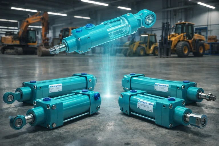
Standard Bore Sizes
FDH series, from the Fenitsa hydraulic catalogue.
| Bore | Bore (in) | Rod options (mm) | Rod options (in) | Rod-end thread | Piston area (cm²) | Pull at 160 bar per rod (t) |
|---|---|---|---|---|---|---|
| Ø40 mm | 1.57 | Ø25 / Ø28 | 0.98 / 1.10 | M16×1.5 | 12.6 | 1.2 / 1.0 |
| Ø50 mm | 1.97 | Ø28 / Ø30 / Ø36 | 1.10 / 1.18 / 1.42 | M20×1.5 | 19.6 | 2.2 / 2.1 / 1.5 |
| Ø63 mm | 2.48 | Ø36 / Ø45 | 1.42 / 1.77 | M27×2 | 31.2 | 3.4 / 2.5 |
| Ø80 mm | 3.15 | Ø45 / Ø56 | 1.77 / 2.20 | M33×2 | 50.3 | 5.6 / 4.2 |
| Ø100 mm | 3.94 | Ø56 / Ø70 | 2.20 / 2.76 | M42×2 | 78.5 | 8.8 / 6.5 |
| Ø125 mm | 4.92 | Ø70 / Ø90 | 2.76 / 3.54 | M48×2 | 122.7 | 13.7 / 9.6 |
| Ø160 mm | 6.30 | Ø90 / Ø100 | 3.54 / 3.94 | M64×3 | 201.1 | 22.4 / 20.0 |
| Ø200 mm | 7.87 | Ø110 / Ø125 | 4.33 / 4.92 | M80×3 | 314.2 | 35.8 / 31.2 |
Each bore in the series is about 1.25 times the previous one, so every step up adds 56–64 % of piston area and push force. The rod options set the pull force and the buckling strength: the thinner rod pulls harder, the thicker rod carries a longer pushing stroke.
Mounting dimensions follow CETOP RP 58 H, with front and rear flanges, rear clevis (plain or with spherical bearing), rod clevis, spherical rod end, centre trunnion and foot mountings. Barrels are honed St52BK+S steel tube; rods are Ck45 steel, hard chrome plated to at least 20 µm and ground to f7 tolerance. Series pages: FDH type, KHS type and THS type cylinders.
Bore to Tons Chart
Theoretical push force on the full piston area, Ø40–Ø200 mm.
F [N] = p [bar] × 0.1 × π × D² [mm] / 4t = F / 9,806.65 · US tons = F / 8,896.44| Bore | 100 bar (1,450 psi) | 160 bar (2,321 psi) | 210 bar — reference only; Fenitsa standard 160 bar, option 250 bar | 250 bar (3,626 psi) |
|---|---|---|---|---|
| Ø40 mm | 1.3 | 2.1 | 2.7 | 3.2 |
| Ø50 mm | 2.0 | 3.2 | 4.2 | 5.0 |
| Ø63 mm | 3.2 | 5.1 | 6.7 | 7.9 |
| Ø80 mm | 5.1 | 8.2 | 10.8 | 12.8 |
| Ø100 mm | 8.0 | 12.8 | 16.8 | 20.0 |
| Ø125 mm | 12.5 | 20.0 | 26.3 | 31.3 |
| Ø160 mm | 20.5 | 32.8 | 43.1 | 51.3 |
| Ø200 mm | 32.0 | 51.3 | 67.3 | 80.1 |
| Bore | 100 bar (1,450 psi) | 160 bar (2,321 psi) | 210 bar — reference only; Fenitsa standard 160 bar, option 250 bar | 250 bar (3,626 psi) |
|---|---|---|---|---|
| Ø40 mm | 1.4 | 2.3 | 3.0 | 3.5 |
| Ø50 mm | 2.2 | 3.5 | 4.6 | 5.5 |
| Ø63 mm | 3.5 | 5.6 | 7.4 | 8.8 |
| Ø80 mm | 5.7 | 9.0 | 11.9 | 14.1 |
| Ø100 mm | 8.8 | 14.1 | 18.5 | 22.1 |
| Ø125 mm | 13.8 | 22.1 | 29.0 | 34.5 |
| Ø160 mm | 22.6 | 36.2 | 47.5 | 56.5 |
| Ø200 mm | 35.3 | 56.5 | 74.2 | 88.3 |
Read the 160 bar column for a standard cylinder and the 250 bar column for the high-pressure option. 210 bar is shown for reference only: Fenitsa cylinders are rated 160 bar as standard, with a 250 bar option, so a 210 bar circuit needs the 250 bar version. The values are theoretical; seal friction and pressure losses in hoses and valves take a few per cent, so leave a reserve of about 10 % between the load and the tabulated force.
One bore size down at 250 bar gives almost the same force as the larger bore at 160 bar, because 250 / 160 = 1.5625 matches the area ratio of neighbouring bores: Ø100 at 160 bar and Ø80 at 250 bar both give 12.8 t.
Force by tonnage, with the calculation, pull force, flow and buckling for each case:
10 ton cylinder
Ø100 mm at 160 bar gives 12.8 t (28 % reserve); Ø80 mm at 250 bar gives 12.8 t. 10 ton hydraulic cylinder
20 ton cylinder
Ø125 mm at 160 bar gives 20.0 t (0.1 % reserve); Ø100 mm at 250 bar gives 20.0 t. For a 10 % reserve: Ø160 mm at 160 bar. 20 ton hydraulic cylinder
30 ton cylinder
Ø160 mm at 160 bar gives 32.8 t (9 % reserve); Ø125 mm at 250 bar gives 31.3 t. 30 ton hydraulic cylinder
50 ton cylinder
Ø200 mm at 160 bar gives 51.3 t (2.5 % reserve); Ø160 mm at 250 bar gives 51.3 t. For a 10 % reserve: Ø200 mm with the 250 bar option. 50 ton hydraulic cylinder
100 ton cylinder
Above the standard series: two Ø160 mm cylinders at 250 bar give 102.5 t, or a special bore is quoted. 100 ton hydraulic cylinder
Inch Bore Equivalents
Fenitsa builds metric bores; this is the nearest match for common inch sizes.
| Inch bore | Inch bore in mm | Nearest Fenitsa bore | Fenitsa bore in inches | Area vs inch bore | Inch bore push at 160 bar (US tons) | Fenitsa bore push at 160 bar (US tons) |
|---|---|---|---|---|---|---|
| 2 in | 50.8 | Ø50 mm | 1.97 | −3.1 % | 3.6 | 3.5 |
| 3 in | 76.2 | Ø80 mm | 3.15 | +10.2 % | 8.2 | 9.0 |
| 4 in | 101.6 | Ø100 mm | 3.94 | −3.1 % | 14.6 | 14.1 |
| 5 in | 127.0 | Ø125 mm | 4.92 | −3.1 % | 22.8 | 22.1 |
| 6 in | 152.4 | Ø160 mm | 6.30 | +10.2 % | 32.8 | 36.2 |
| 8 in | 203.2 | Ø200 mm | 7.87 | −3.1 % | 58.3 | 56.5 |
Four of the six inch sizes have a metric neighbour only 3 % smaller in area; the 3 inch and 6 inch bores sit between metric sizes, so the next larger bore (Ø80 or Ø160 mm) is used and gives about 10 % more force.
How many tons can a 4, 5 or 6 inch cylinder push? At 160 bar: 14.6, 22.8 and 32.8 US tons. Many inch-sized cylinders are rated for 3,000 psi (207 bar); at that pressure the same bores push 18.8, 29.5 and 42.4 US tons. A metric replacement for a 3,000 psi circuit is specified with the 250 bar option.
When replacing an inch cylinder, rod diameter, pin sizes, port threads and retracted length must fit too — send us the old cylinder’s dimensions.
Standard Strokes and Maximum Stroke
The standard FDH strokes are 100, 200, 300, 400 and 500 mm. The maximum stroke is 5,000 mm; other strokes up to that limit, including exact inch strokes, are quoted to order. The KHS and THS series are listed with strokes up to 3,000 mm.
| Stroke (in) | Stroke (mm) | Nearest standard step |
|---|---|---|
| 12 in | 304.8 mm | 300 mm (4.8 mm shorter) |
| 24 in | 609.6 mm | Beyond the 500 mm step |
| 36 in | 914.4 mm | Beyond the 500 mm step |
| 72 in | 1,828.8 mm | Beyond the 500 mm step |
Long pushing strokes need a rod that will not buckle, and every metre of stroke adds oil volume: a Ø100 mm bore takes 7.9 L per metre on the extend stroke. The long stroke hydraulic cylinders page covers rod selection, mounting factors and worked examples up to 5,000 mm.
5 Ton and 200 Ton Cylinders
The two ends of the tonnage range.
| Force | Pressure | Calculated bore | Standard bore | Force of the standard bore |
|---|---|---|---|---|
| 5 t | 160 bar | Ø62.5 mm | Ø63 mm | 5.1 t / 5.6 US tons |
| 5 t | 250 bar | Ø50.0 mm | Ø50 mm | 5.0 t / 5.5 US tons |
| 200 t | 160 bar | Ø395.1 mm | Outside the standard series | Built to order, per project |
| 200 t | 250 bar | Ø316.1 mm | Outside the standard series | Built to order, per project |
How to Choose a Size
The short version of our hydraulic cylinder sizing guide.
- 1
Define the force
Real load plus friction and acceleration, then a reserve of about 10 %. Note whether the cylinder pushes, pulls or both.
- 2
Fix the pressure
The pressure that actually reaches the cylinder: 160 bar standard, up to 250 bar with the option.
- 3
Pick the bore
Required bore D = √(4F / πp); round up to the next standard size in the chart above, or use the force calculator.
- 4
Choose the rod
Check pull force on the rod-side area and rod buckling at full extension.
- 5
Set stroke and mountings
The mounting sets the buckling length; the stroke sets oil volume and closed length.
- 6
Check speed and flow
Flow Q = A × v; the piston speed of the standard series is limited to 0.5 m/s. The flow rate calculator gives pump flow for your speed.
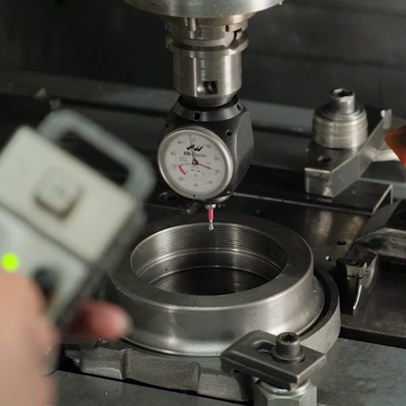
Send Us Your Cylinder Data
Bore, rod, stroke, working pressure, mountings and quantity — or a drawing or photo of the cylinder you want to replace. Our engineers reply with a technical proposal and a quotation. info@fenitsa.com.
Hydraulic Cylinder Sizes – FAQ
Short answers from our engineers.
What are the standard hydraulic cylinder bore sizes?
In the Fenitsa FDH series the standard bores are Ø40, 50, 63, 80, 100, 125, 160 and 200 mm, which is 1.57 to 7.87 inches. Each bore has two or three rod options between Ø25 and Ø125 mm. Larger bores are built to order.
How do you work out tonnage for a hydraulic ram?
Multiply the piston area by the pressure. In metric units, tonnes = bar × bore² (in cm) ÷ 1,249; a Ø100 mm ram at 160 bar gives 160 × 100 ÷ 1,249 = 12.8 t. In imperial units, US tons = psi × piston area in square inches ÷ 2,000. The hydraulic cylinder force calculator does both.
How many tons can a 5 inch hydraulic cylinder push?
A 5 inch bore has 19.63 in² of piston area. At 160 bar (2,321 psi) it pushes 22.8 US tons (20.7 t); at 3,000 psi it pushes 29.5 US tons. The nearest Fenitsa bore, Ø125 mm, pushes 22.1 US tons at 160 bar.
Do you make hydraulic cylinders in inch sizes?
The Fenitsa standard series is metric. When a machine was designed around an inch bore, we select the nearest metric bore, check that force, speed and fit still work, and confirm it in the quotation. Send the dimensions of the old cylinder — how to measure a hydraulic cylinder shows which ones.
Is a smaller bore at 250 bar as good as a bigger bore at 160 bar?
For push force it can be identical: Ø160 mm at 250 bar and Ø200 mm at 160 bar both push 51.3 t. The smaller cylinder needs 36 % less oil per stroke, but the pump, valves and hoses must be rated for 250 bar and the cylinder ordered with the 250 bar option.
Related Pages
Hydraulic Cylinder Sizing
Step-by-step selection of bore, rod, stroke and mountings.
Hydraulic Cylinder Force Calculator
Push and pull force for any bore and pressure.
Long Stroke Hydraulic Cylinders
Rod buckling and mounting factors for strokes up to 5,000 mm.
50 Ton Hydraulic Cylinder
Ø200 at 160 bar or Ø160 at 250 bar, with pull and flow data.