

 Türkçe
 Русский
 Español
 العربية
How Does a Hydraulic Cylinder Work?
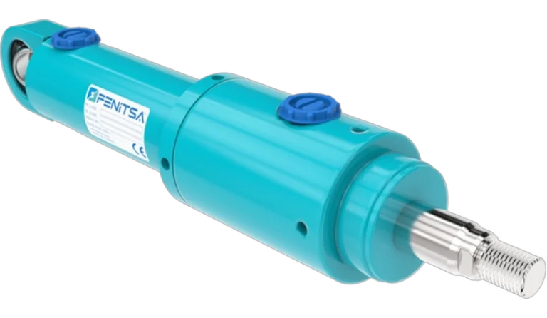
A hydraulic cylinder is a linear actuator that turns oil pressure into a straight push or pull. A pump sends oil into one end of the barrel, the pressure acts on the piston, and the piston rod carries the resulting force — pressure × piston area — to the load. Reversing the oil flow drives the rod back.
The same principle drives every hydraulic cylinder, from a workshop jack to an excavator boom. This page explains it with a diagram and a worked force example; the types and parts guides go into the details.
Pascal’s Law in Three Lines
- Pressure applied to a confined liquid acts equally in every direction and on every surface.
- Oil hardly compresses, so the pump’s flow moves the piston while the pressure pushes it.
- Force equals pressure times area, so a moderate pressure on a large piston produces a large force.
F = p × AA = π × D² / 4v = Q / AIn practical units, F [N] = p [bar] × 0.1 × A [mm²]. At 160 bar every square centimetre of piston carries 1,600 N — the weight of about 163 kg. Multiply that by the area of a real piston and the force quickly reaches tonnes.
The Extend and Retract Cycle
One full cycle of a double acting cylinder.
- Rear cap (cap end)
- Rear clevis mounting
- Port A — cap end (full bore side)
- Barrel (honed cylinder tube)
- Tie rods and nuts
- Piston
- Piston seal
- Wear (guide) rings
- Piston rod (hard chrome plated)
- Front head (gland)
- Rod bearing (guide bush)
- Rod seal
- Wiper (scraper)
- Port B — rod end (annulus side)
- Cushioning spear and adjusting screw
- Static O-rings
- Rod eye
Cap-side chamber — pressure acts on the full piston area · Rod-side chamber — pressure acts on the annulus area
- 1
Valve shifts to port A
The directional valve connects the pump to port A at the cap end and opens port B to the tank.
- 2
The rod extends
Oil fills the cap-side chamber and pushes on the full piston area. The rod moves out, and the oil in front of the piston flows out of port B back to the tank.
- 3
End of stroke
The cushion slows the piston. If the load stops the cylinder, pressure rises until the relief valve opens and the cylinder holds its maximum force.
- 4
Valve reverses
Pump flow goes to port B. Pressure acts on the annulus around the rod, so the cylinder retracts with less force but more speed.
- 5
Valve centred
Both ports are blocked, oil is trapped on both sides and the piston holds its position — as long as seals and valve do not leak.
A single acting cylinder skips the fourth step: the load, gravity or a spring pushes it back when its only port opens to tank. The types of hydraulic cylinders guide compares the designs; see also double acting and single acting cylinders.
Where the Force Comes From
The force is pressure times the area it acts on: the full piston area on the extend stroke, the piston area minus the rod area on the retract stroke. The pressure itself is set by the load — the pump only builds as much pressure as the load resists, up to the relief valve setting.
Example: a Ø80 mm piston has an area of 50.3 cm². At 160 bar (2,321 psi) it pushes 80.4 kN — 8.20 metric tonnes or 9.04 US tons. On the return stroke the Ø45 mm rod takes 15.9 cm² away, leaving 34.4 cm² and a pull force of 55.0 kN (5.61 t).
| Pressure | psi | Push (kN) | Push (t) | Pull (kN) | Pull (t) |
|---|---|---|---|---|---|
| 50 bar | 725 | 25.1 | 2.56 | 17.2 | 1.75 |
| 100 bar | 1,450 | 50.3 | 5.13 | 34.4 | 3.50 |
| 160 bar | 2,321 | 80.4 | 8.20 | 55.0 | 5.61 |
| 250 bar | 3,626 | 125.7 | 12.81 | 85.9 | 8.76 |
Speed follows the flow, v = Q / A. A pump delivering 40 L/min extends this cylinder at 133 mm/s and retracts it at 194 mm/s. For other sizes use the hydraulic cylinder force calculator.
Cushioning, Seals and Speed
Cushioning brakes the piston in the last part of the stroke: a spear on the piston enters the end cover, traps oil and forces it out through an adjustable needle, so the piston slows before it touches metal and the machine is spared the shock.
Seals keep the pressure where it belongs — the piston seal between the chambers, the rod seal and wiper in the head, static O-rings at fixed joints — while wear rings keep piston and rod centred. The hydraulic cylinder parts guide shows every seal on a labelled diagram.
Speed is controlled by flow, not pressure: flow control valves meter the oil, and counterbalance valves stop an overrunning load from running away as it lowers. Fenitsa FDH cylinders are rated for piston speeds up to 0.5 m/s and, with standard NBR seals, for −20 °C to +80 °C.
What Can Go Wrong
Five common faults and what they point to.
- Drift under loadThe rod creeps with the valve closed: oil is passing a worn piston seal or the valve is leaking. With the load removed and the piston at the end of stroke, pressurise one side and open the other port — steady flow means a piston seal leak.
- External leaksOil on the rod or at the head points to a worn rod seal, a scored rod or a damaged wiper; oil at a joint points to an O-ring.
- Bent rodBuckling on a long push stroke or side load. The rod must suit the stroke and mounting — see the sizing guide.
- Jerky or slow motionAir in the oil, too little flow or high seal friction; bleeding the air and checking the pump flow usually cure it.
- OverheatingOil above the seal rating hardens the seals. Standard NBR seals cover up to +80 °C; Viton seals are the option for higher temperatures.
Most failures start with dirty oil or side load. Knowing the parts of a hydraulic cylinder helps find the cause, and the types guide shows which designs are easiest to reseal.
Send Us Your Cylinder Data
Bore, rod, stroke, working pressure, mountings and quantity — or a drawing or photo of the cylinder you want to replace. Our engineers reply with a technical proposal and a quotation. info@fenitsa.com.
How Hydraulic Cylinders Work – FAQ
Short answers from our engineers.
What are hydraulic cylinders used for?
Hydraulic cylinders produce straight-line force wherever heavy loads must be lifted, pushed, pressed or clamped: excavators, loaders, cranes, tippers, presses, injection moulding machines, lifts, farm machinery and dam gates. They are chosen when the force is too large for a pneumatic or electric actuator of the same size.
Is a hydraulic ram the same as a hydraulic cylinder?
In everyday use, yes: “hydraulic ram” is the common British and Australian name, and “hydraulic piston” is also used. Strictly, a ram is a plunger cylinder whose rod is the working area. “Linear actuator” covers anything that produces straight-line motion; a hydraulic jack is a cylinder with its own hand pump.
Why does a hydraulic cylinder retract faster than it extends?
Because the rod takes up space on the rod side, the same flow fills a smaller volume and the piston moves faster, but with less force. A Ø80 mm cylinder with a Ø45 mm rod retracts about 1.46 times faster than it extends and pulls with 68 % of its push force.
Does a hydraulic cylinder need a pump?
Yes. The cylinder only converts pressure into force; a pump supplies the flow and a directional valve decides which port it goes to. The pump can be driven by an electric motor, an engine or by hand, as in a hydraulic jack, and a relief valve limits the pressure.
Can a hydraulic cylinder hold a load with the pump switched off?
For a while, but not indefinitely. A closed valve traps the oil, yet valves and seals leak slightly and the load slowly creeps. Where a load must be held safely, a pilot-operated check valve or a counterbalance valve is mounted directly on the cylinder.
What is the difference between a hydraulic and a pneumatic cylinder?
A hydraulic cylinder uses oil, which hardly compresses, so it gives large, stiff and precisely controlled force; Fenitsa FDH cylinders work at 160 bar. A pneumatic cylinder runs on compressed air — Fenitsa’s at 1.5–10 bar — so it is lighter, faster and cleaner, but much weaker and springier.
Related Pages
Types of Hydraulic Cylinders
Single and double acting, telescopic, tie rod, welded and plunger designs.
Hydraulic Cylinder Parts and Components
A labelled diagram of every part and seal.
Hydraulic Cylinder Sizing
Bore, rod and stroke for your load and speed.
Hydraulic Cylinder Force Calculator
Push and pull force in kN, tonnes and lbf.