

 Türkçe
 Русский
 Español
 العربية
Hydraulic Cylinder Parts and Components
A hydraulic cylinder is built from a barrel, a piston and piston rod, a front head (gland) and rear cap, seals, ports and a mounting at each end, held together by tie rods or welds. The piston and its seals divide the barrel into two chambers; the head guides and seals the rod where it leaves the cylinder.
The labelled diagram below shows 17 parts of a double acting tie rod hydraulic cylinder. Each section explains what the part does, what it is usually made of and how it fails; values for Fenitsa’s FDH series come from our catalogue.
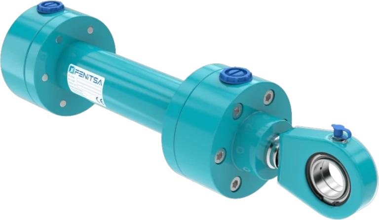
Hydraulic Cylinder Diagram
17 numbered parts of a double acting tie rod cylinder.
The cross-section is numbered from the rear mounting to the rod eye. A welded cylinder has the same internal parts; only the tie rods (5) are replaced by a welded cap and a threaded or bolted head.
- Rear cap (cap end)
- Rear clevis mounting
- Port A — cap end (full bore side)
- Barrel (honed cylinder tube)
- Tie rods and nuts
- Piston
- Piston seal
- Wear (guide) rings
- Piston rod (hard chrome plated)
- Front head (gland)
- Rod bearing (guide bush)
- Rod seal
- Wiper (scraper)
- Port B — rod end (annulus side)
- Cushioning spear and adjusting screw
- Static O-rings
- Rod eye
Cap-side chamber — pressure acts on the full piston area · Rod-side chamber — pressure acts on the annulus area
Barrel (Cylinder Tube)
The barrel is the pressure vessel. Its bore is honed smooth and straight because the piston seal slides on it every stroke; any scoring becomes a leak path between the chambers. Wall thickness follows bore and pressure.
Fenitsa FDH barrels are honed St52BK+S steel tube, a cold-drawn, stress-relieved grade chosen for accurate bore geometry. Scoring from dirty oil or a failed wear ring shows up as drift or lost force, not as an external leak.
Piston
The piston is the disc that divides the barrel into two chambers and turns oil pressure into force. It is fixed to the rod with a nut or a locked thread and carries the piston seal between two wear rings. “Hydraulic piston” often means the whole cylinder; in engineering terms it is only this part.
A double acting piston seals both ways, a single acting one only one way, and a cushioned cylinder adds a spear or sleeve (15). Most pistons are machined from steel or cast iron. Failure signs: worn seal grooves, a loose nut that knocks at the stroke end, scoring where a wear ring failed.
Piston Rod
The piston rod carries the force out of the cylinder and is the part most exposed to damage. It is ground and hard chrome plated so the rod seal runs on a hard, smooth, corrosion-resistant surface. Its diameter is usually set by buckling — see the sizing guide.
Fenitsa FDH rods are Ck45 steel with hard chrome ≥ 20 µm and f7 tolerance, supplied as HR (hardened and chromed), SS (stainless) or CR (Ck45 chromed). Scratches, pitting and flaking chrome cut the rod seal; a bent rod means buckling or side load.
| Bore | Rod options | Rod-end thread |
|---|---|---|
| Ø40 mm | Ø25 / Ø28 mm | M16×1.5 |
| Ø50 mm | Ø28 / Ø30 / Ø36 mm | M20×1.5 |
| Ø63 mm | Ø36 / Ø45 mm | M27×2 |
| Ø80 mm | Ø45 / Ø56 mm | M33×2 |
| Ø100 mm | Ø56 / Ø70 mm | M42×2 |
| Ø125 mm | Ø70 / Ø90 mm | M48×2 |
| Ø160 mm | Ø90 / Ø100 mm | M64×3 |
| Ø200 mm | Ø110 / Ø125 mm | M80×3 |
Front Head (Gland) and Rear Cap
The front head, or gland, closes the rod end. From the inside out it carries a static O-ring, the guide bush, the rod seal and the wiper. Once the bush wears, the rod moves sideways and the rod seal leaks.
The rear cap closes the other end and usually carries port A and the rear mounting. Tie rods clamp both to the barrel; on a welded cylinder the cap is welded on and the head threaded or bolted in. See also cylinder front and rear covers.
Seals
Seals are the parts that wear out: dynamic seals slide, static O-rings sit between fixed parts.
| Seal | Function | Typical material | Failure sign |
|---|---|---|---|
| Piston seal (7) | Separates the two chambers | PU, or PTFE-based with an NBR energiser | Drift under load, lost force |
| Rod seal (12) | Keeps oil in at the rod | PU or PTFE-based; NBR | Oil film or drips on the rod |
| Wiper (13) | Scrapes dirt off the retracting rod | PU | Scored rod, early rod seal wear |
| Wear rings (8), guide bush (11) | Keep piston and rod centred | PTFE-based or fabric resin; bronze bushes | Scored barrel or rod |
| Static O-rings (16) | Seal fixed joints | NBR; FKM (Viton) for heat | Weeping at a head or cap joint |
NBR suits mineral oil at normal temperatures, FKM (Viton) takes heat, PU is hard-wearing and PTFE-based compounds give low friction. Fenitsa FDH cylinders use NBR seals as standard (code NS) for −20 °C to +80 °C; Viton (code VS) is the option, and special seals cover −30 °C to +200 °C.
Cushioning
Cushioning slows the piston in the last part of the stroke. A spear or sleeve (15) enters a bore in the end cover and closes the main outlet, so the trapped oil escapes only through a channel set by an adjusting screw; a check valve lets full flow back in for the return.
Cushions suit heavy or fast loads that stop inside the cylinder; they do not replace a flow control valve. Fenitsa FDH cylinders are rated for piston speeds up to 0.5 m/s.
Ports
Port A at the cap end and port B at the rod end (3 and 14) let the oil in and out; a single acting cylinder has one port and a breather. Too small a port limits speed and causes heat.
Common threads are BSP (G), metric, NPT and SAE O-ring boss; large cylinders use flange ports. On a replacement the ports must also face the hoses. For Fenitsa cylinders, size, thread and position are confirmed in the quotation; how to measure a hydraulic cylinder shows how to record them.
Tie Rods or Welds
Something must hold the head and cap on against the full pressure force — 125.7 kN on a Ø100 mm cylinder at 160 bar. Tie rods (5) clamp them with pre-tensioned nuts, so the cylinder can be taken apart completely. On a welded cylinder the cap is welded on and the head threaded or bolted in, giving a slimmer, more shock-resistant body.
The tie rod hydraulic cylinders page compares both designs; welded hydraulic cylinders covers mobile machines.
Mounts and Rod Ends
Mountings fix the cylinder to the machine; rod ends connect the rod to the load. Pinned mountings (clevis, spherical eye, trunnion) let the cylinder swing; fixed ones (flange, foot) need accurate alignment. A spherical bearing tolerates small misalignment.
| Code | Mounting | Position |
|---|---|---|
| FFM | Front flange | Head end |
| RFM | Rear flange | Cap end |
| RSM | Rear clevis | Cap end |
| RHM | Rear clevis with spherical bearing | Cap end |
| CTM | Centre trunnion | Middle of the barrel |
| FMM | Foot | Along the barrel |
| FSM | Rod-end clevis | Rod end |
| FRM | Rod-end spherical bearing | Rod end |
FDH mounting dimensions follow CETOP RP 58 H; front and rear trunnions are also listed. See hydraulic cylinder mounting options and rod ends.
Hydraulic Cylinder Parts List
Numbers match the diagram.
| No. | Part | Function | Replaced at a reseal? |
|---|---|---|---|
| 1 | Rear cap (cap end) | Closes the cap end | If damaged |
| 2 | Rear clevis mounting | Pins the cylinder to the frame | Pin and bush if worn |
| 3 | Port A — cap end (full bore side) | Oil in to extend | No |
| 4 | Barrel (honed cylinder tube) | Holds the pressure | If scored |
| 5 | Tie rods and nuts | Clamp head and cap to the barrel | If stretched |
| 6 | Piston | Turns pressure into force | If damaged |
| 7 | Piston seal | Seals between the chambers | Yes — seal kit |
| 8 | Wear (guide) rings | Centre the piston | Yes — seal kit |
| 9 | Piston rod (hard chrome plated) | Carries the force to the load | If scored, pitted or bent |
| 10 | Front head (gland) | Closes the rod end | If damaged |
| 11 | Rod bearing (guide bush) | Guides the rod | If worn |
| 12 | Rod seal | Keeps oil in | Yes — seal kit |
| 13 | Wiper (scraper) | Keeps dirt out | Yes — seal kit |
| 14 | Port B — rod end (annulus side) | Oil in to retract | No |
| 15 | Cushioning spear and adjusting screw | Slows the piston at the stroke end | If damaged |
| 16 | Static O-rings | Seal the fixed joints | Yes — seal kit |
| 17 | Rod eye | Connects the rod to the load | Bearing if worn |
Send Us Your Cylinder Data
Bore, rod, stroke, working pressure, mountings and quantity — or a drawing or photo of the cylinder you want to replace. Our engineers reply with a technical proposal and a quotation. info@fenitsa.com.
Hydraulic Cylinder Parts – FAQ
Short answers from our engineers.
How do you identify hydraulic cylinder seals?
Measure the groove, not the old seal: record the rod or bore diameter, the groove diameter and width, and the seal profile and material. Old seals are often worn or swollen. A nameplate part number usually identifies the seal kit directly.
What is the difference between a piston and a piston rod?
The piston is the disc inside the barrel that the oil pushes on; the piston rod is the shaft fixed to it that leaves the cylinder and moves the load. The piston carries its seal and wear rings; the rod runs through the head’s bush, rod seal and wiper.
What is the gland on a hydraulic cylinder?
The gland is the front head through which the rod leaves the cylinder. It holds the guide bush, rod seal, wiper and a static O-ring, and on welded cylinders it is threaded or bolted in so the seals can be replaced.
Why are hydraulic cylinder rods chrome plated?
Hard chrome gives the rod a hard, smooth, corrosion-resistant surface for the rod seal to run on; a rough or rusty rod cuts the seal quickly. Fenitsa FDH rods are Ck45 steel with hard chrome ≥ 20 µm and f7 tolerance, with hardened and stainless steel rods as options.
What is a hydraulic cylinder barrel made of?
Usually cold-drawn steel tube, honed inside. Fenitsa FDH barrels are honed St52BK+S tube, a cold-drawn, stress-relieved steel that keeps the bore round and straight, so the piston seal lasts.
Can I replace only the seals instead of the whole cylinder?
Yes, if the rod and barrel are undamaged: a seal kit replaces the piston seal, rod seal, wiper, wear rings and O-rings. If the rod or barrel is scored, or the rod is bent, new seals fail quickly. Fenitsa provides service and spare-parts support for 10 years.
Related Pages
Types of Hydraulic Cylinders
Single and double acting, telescopic, tie rod, welded, plunger and double rod.
How Does a Hydraulic Cylinder Work?
The extend and retract cycle and where the force comes from.
How to Measure a Hydraulic Cylinder
Eight measurements for ordering a replacement.
Hydraulic Cylinder Mounts and Rod Ends
Clevis, spherical eye, flange, foot and trunnion mountings.